TOOLS REQUIRED
|
|
|
PARTS AND KITS INCLUDED
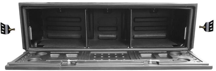
- AeroBox™
- (2) Keyed Cam Locks
- Load floor
- (2) Strikers and Claw Latches
KIT #1
KIT #2A - Tie-Down Hardware
|
KIT #2B - Striker Bracket
|
Before You Get Started...

Any Modification or unintended use will void the manufacturers warranty
|

A dry fit must be performed before the final installation of the product to ensure fit
|

Presence of a drop-in bed liner may neccesitate some modification of the bed liner for proper function
|
AEROBOX INSTALLATION VIDEO TUTORIAL
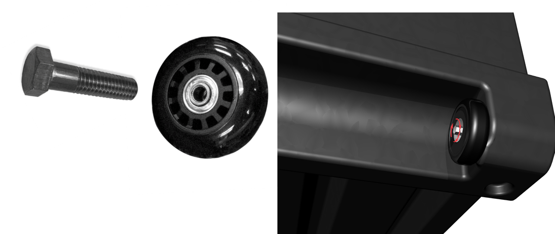
WHEEL INSTALLATION
|
|
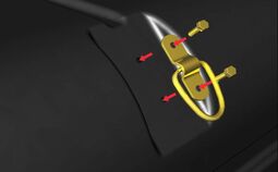
TIE-DOWN RING INSTALLATION
- Place the AeroBox™ right side up so you can access the aerodynamic (rounded) side of the AeroBox™.
- Locate drill centering marks at each tie down location and drill a 17/64” hole at each mark.
- Insert ring in bracket recess and place assembly so holes align with drilled holes on AeroBox™.
- Insert ¼”-20 X 5/8” hex bolts through the holes toward the inside of the box. Place a ¼”washer and ¼”-20 Nylock™ nut on the end of each bolt from the inside of the box and tighten.
- Repeat this process for the remaining 2-tie-downs, tightening each bolt assembly with 7/16” socket and wrench. The rings should move freely in the brackets.
STRIKER BRAKET INSTALLATION
|
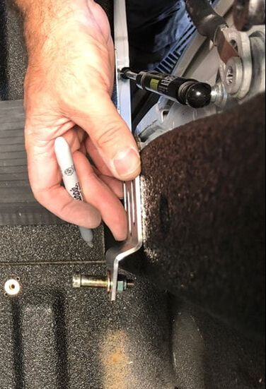
1. Check fit by placing AeroBox™ in upright position and sliding it into the tailgate opening of your truck until the door of the AeroBox™ would be flush with the tailgate when the tailgate is closed, but does not inhibit closure. The AeroBox™ should be centered in the opening. Make sure there will be no interference with closing the tailgate by closing the tailgate with the box in position.
|
|
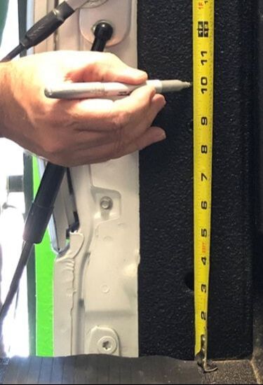
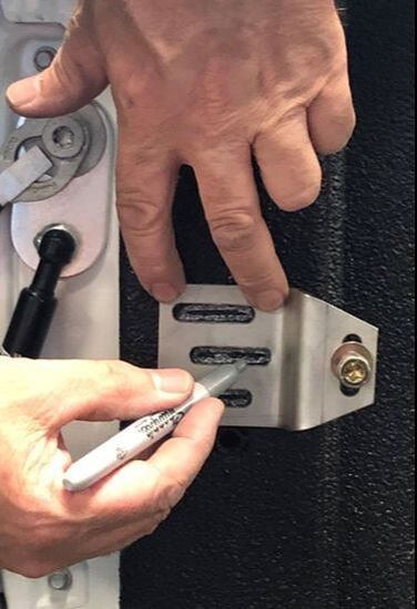
2. Measure 10 ¼” from the bed floor up the tailgate opening rail and mark the location. Position the striker bracket with the offset towards centerline of the truck over the mark such that the center slot is centered vertically over the mark. Mark the interior of each slot.
Note: The back edge of the bracket should typically be nearly flush with the back edge of the tailgate opening rail in most cases. Positioning it more forward on the rail will increase the gap between the box and the tailgate, which may be necessary in some cases where there is interference with closing the tailgate. In some cases where there is minimal flat mounting area on the tailgate opening rail, the fore-aft position of the bracket should maximize engagement with the flat area. However, the rear edge of the bracket should never be rearward of the rear edge of the tailgate opening rail.
Note: The back edge of the bracket should typically be nearly flush with the back edge of the tailgate opening rail in most cases. Positioning it more forward on the rail will increase the gap between the box and the tailgate, which may be necessary in some cases where there is interference with closing the tailgate. In some cases where there is minimal flat mounting area on the tailgate opening rail, the fore-aft position of the bracket should maximize engagement with the flat area. However, the rear edge of the bracket should never be rearward of the rear edge of the tailgate opening rail.
STEP 1
|
STEP 2
|
STEP 3
|
|
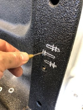
3. Mark locations for drilling attachment holes centered vertically within each slot. Offset fore-aft locations of marks between center slot and top and bottom slots for greatest bracket retention strength. Center punch each marked location to aid drilling, so bit does not wander from your mark. Drill a 25/64” hole at each location (3/8” drill bit will work if you don’t have a 25/64”).
Note: Leave some space from the end of each slot with your marking to allow for some fore-aft adjustment of the bracket. Hint: If a plastic liner is present, drill holes through liner and sheet metal. |
|
|
|
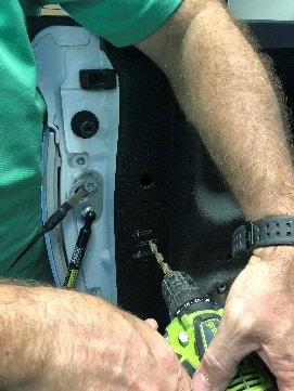
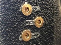
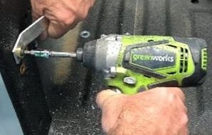
4. To secure threaded inserts, assemble a washer on a ¼”-20 cap screw and extend screw through the hole in threaded insert assembly tool. Thread insert on to screw until tight and place the insert through the previously drilled holes. Grasp threaded insert assembly tool tightly to keep it from rotating and flush with sheet metal while tightening screw with T25 Torx driver (impact driver preferred) until threaded insert is fully compressed (clamped tight on to sheet-metal). Be careful not to overtighten to avoid stripping threads. Unscrew the cap screw when finished and repeat for other inserts.
Note: Screw/Bolt will be difficult to turn at first, gets easier as insert begins to compress, then very difficult when fully compressed. A ¼”-20 hex head bolt can be substituted for this step with a socket wrench or impact wrench. An extra cap head screw has been included in case one is damaged. |
|
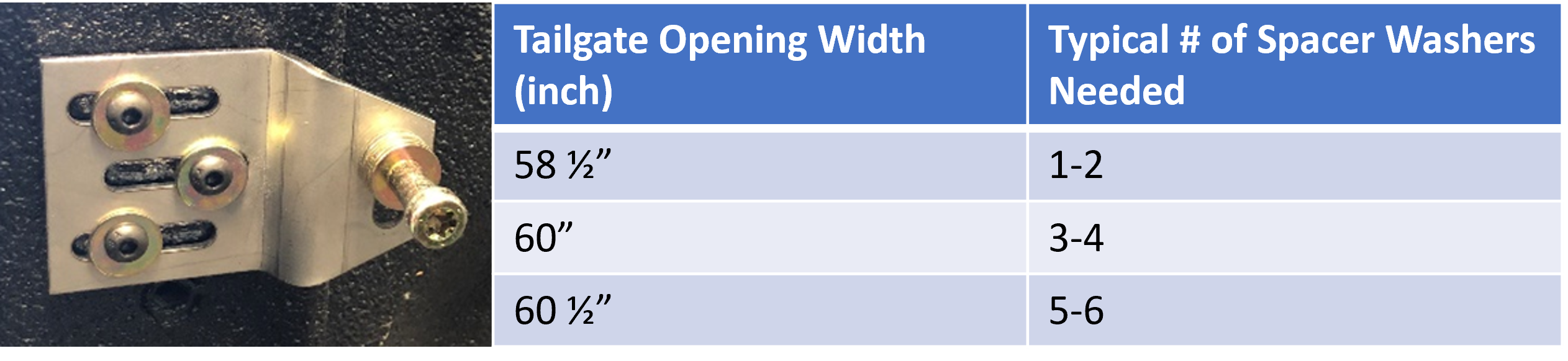
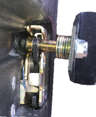
5. Install a striker on each bracket, with the striker head on the side of the bracket offset toward centerline of truck, per example image. If necessary, adjust the striker length by and adding spacer washers to the stem of the striker. The number of washers will depend on the width of the tailgate opening of your truck per the included table. Secure the striker with a 5/16-18 Nylock™ nut and T45 Torx wrench (or vise grips).
6. Install the striker brackets using washers and ¼”-20 cap head screws at each threaded insert location (brackets work for either side). Loosely tighten each screw.
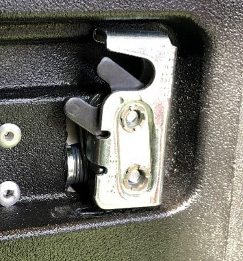
7. Install the AeroBox™ by sliding the box forward in the bed while roughly aligning the
claw latches on either side of the box with the installed strikers. The strikers should align vertically with the recessed channel on the sides of the boxes, leading to the claw latch. They should also engage the claw latches when the mushroom head of each striker is able to clear to the inside of each latch simultaneously, as shown.
|
|
8. If necessary, adjust the height of the striker by loosening the striker nut and adjusting its position in the vertical slot until it is centered vertically in the alignment channels on the AeroBox™ and the latch mechanism (typically 10 ¼” from top surface of bed floor). Tighten nut securely
9. In most cases, no fore-aft adjustment of the striker brackets should be necessary. However, some adjustment is possible by loosening the attachment screws and slide the bracket forward or rearward within the available slot length.
10. After all adjustments are made, the AeroBox™ should smoothly engage the latches simultaneously and “click” in place. Make sure all nuts are tight. Re-check tightness occasionally.
11. The box can be “disengaged” and easily removed from the bed by opening the door and lifting on each of the release handles. Once released, close and latch the door and use the door grab handle and/or sides of the box to slide out your AeroBox™ and roll it away to wherever it is needed!
DIVIDER PANEL INSTALLATION & REMOVAL
|
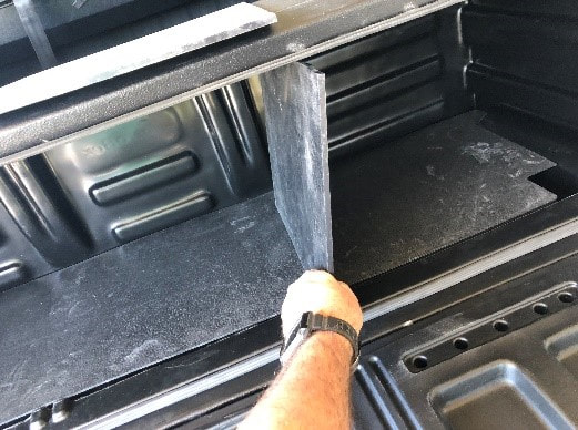
Your Premium Aerobox™ comes with two divider panels for adjustability to secure large or small items. These panels are installed by aligning them with the grooves on the bottom of the door opening and tilting them slightly to the side while sliding them forward. Once almost fully forward, tilt them back to vertical and lock them in to the grooves. Removal is in reverse order.
|
|
IMPROPER USE WARNING
Placing very heavy items in the AeroBox™ combined with rough terrain and/or heavy braking could result in your AeroBox™ coming loose and/or damage to the attachment assembly. Additional tie downs may be necessary in these situations